 |
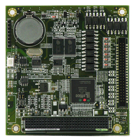
FleetPC-3 module CAN-BUS, Digital I/O, SRAM (PCI 104) [http://www.cartft.com/catalog/il/1306] |
|
FleetPC-3 module CAN-BUS, Digital I/O, SRAM (PCI 104) [http://www.cartft.com/catalog/il/1306] |
|
39.00 EUR
incl. 19% VAT, plus shipping
|
| PCI104 digital I/O, SRAM disk & CAN bus module | |
| PCB | 4-layer PCB |
| General | |
| Bus interface | PCI 104, PCI 2.0 compliant |
| Controller | FPGA & Standalone CAN controller |
| SRAM disk | - 2 x 512KB low power SRAM - 1M Byte as one bank - Battery backup by optional module - Battery power consumption: less than 15uA - Operation modes: A. Memory Mode i. Independent mode ii. Replicate mode B. Disk Mode (is only supported in Linux) C. Mode selection through Jumper (factory default disk mode) |
| Digital Input | - 12 channels - Internal pull up - Programmable de-bounce time (0 ms to 255ms, 1 ms resolution). True after X ms of constant state. - Support Change of State interrupt - 5000Vrms optical isolation - Response time: 20uS (without de-bounce) - Rising trigger or falling trigger - Suggested maximum input frequency 10KHz( duty = 50% ). - Signal input : A. Open/Ground switch input B. Digital Logic i. Logic High: 3V to 28V ii. Logic Low: 0V to 1.5V |
| Digital Output | - 12 channels - Output Type: Open drain MOSFET driver - Output voltage range: 5V to 30V - Sink Current: maximum 500mA each channel - Power on initial state: MOSFET off - Support pulse generator : A. Programmable cycle time, duty cycle and number of cycles. User defines on and off periods (maximum 8-bit for on and off period value). B. Maximum 65535 cycles C. RUN & STOP command D. Resolution: 1 ms, 100ms and 1 second |
| Timer | - 12 x independent 16-bit timers - Support Time Out Interrupt - Resolution: 1 ms and 100ms second(Resolution: 1ms, and 100ms) |
| Counter | - 12 x independent 16-bit counters - Connect to all digital inputs - Operation Mode: a. Count to number interrupt. b. Read and clear c. Read on the fly d. Auto stop counting after programmable constant state interval(Interrupt active after programmable constant state interval Resolution: 1ms, and 100ms) e. Count over to target interrupt. |
| CAN bus | - Connect to FPGA SPI bus - 1 x CAN bus - 2KV isolation - CAN 2.0B Active protocol - Controller: Microchip MCP2515(Industrial grade -40 to 85'C) - Transceiver: Micro chip MCP2551(Industrial grade -40 to 85'C) [Other Transceiver manufacturers: Philips, TI, Maxim, ST, Infineon, Atmel] - 2 pin JST connector(2 pin JST 2.0mm connector ) - Programmable baud rate: from 5K bps Maximum 1M bps or user-defined baud rate - Time stamp of CAN message - API library for user development - CAN bus device status query |
| Power input | From PCI 104 |
| Maximum card | Maximum 2 cards can be stacked up in one system |
| Jumper | - INT# & ID select. Please see Appendix. - SRAM chip capacity select (Used for when auto detection doesn't work only) |
| Digital I/O connector | - 44 pin 2.0 mm pitch 180 degree with box - Pin Assignment: Appendix 3(Pin assignment modify) |
| Software | - Windows XP, XPe and Linux device driver and API - Windows XP, XPe and Linux demo program - User interface for DIO, SRAM and CAN bus in Linux and Windows XP embedded |
| Mechanical | |
| Dimensions | 90.17 x 95.89mm (3.55"x3.775") |
| Operating temperature | -20oC to 70oC (-1~158oF) without air flow |
| Storage temperature | -20~85oC (-4~185oF) |
| Relative Humidity | 0 to 90% @ 40°C, non-condensing (95% @ 40°C, Non-Condensing by request) |
| Scope of supply | |
| 1x | PCI 104 Controller card |
| 1x | 150mm Digital I/O cable |
| 1x | 150mm 2-wire cable for CAN bus |